 |
 |
 |
 |
 |
 |
 |
 |
 |
 |
Other ideas Fabc  |
|||||||||
The gyroscopic gear is an automatic gear-box that uses gyroscopic inertia as driving force.
The blue shafts are an input and an output shaft, so a driving and a driven shaft, one connected with an engine (your legs can be that motor), the other with the wheel or machine that needs to be driven.
Point with the mouse at the second and third button to see the inside of the gear-mechanism. In the center, 4 conic cog-wheels gear into each other, rotating on an axle-cross.
Both blue shafts are related through the red, rather heavy, cog-wheel couple.
This cog-wheel couple can also rotate as a whole around in- and out-going axles. Point with the mouse at the first button to see that movement. The driven shaft now is not rotating.
The heavy red cog-wheels act as gyroscopes which means that, when rotating, they will resist against changing the direction of their axle.
When the force needed to change the direction of the axle of the red gyroscopes is bigger than the force needed to drive the driven blue shaft, then last shaft will rotate and the machine will be driven.
The gyroscopes then, at a certain rotation-speed of the motor, form a flexible connection between motor and driven wheel. If for example the driven wheel must climb a hill, then its rotation-speed slows down while the traction proportionally becomes bigger. The gyroscope-couple then of course also rotates (faster) around in- and output shafts.
The force that can be transported this way depends on the maximum rotation-speed of the red wheels but also of their mass.
Whether this gear-mechanism also can be of practical value to drive a car, I do not know. That mainly depends on the weight of the gyroscopic wheels, I think. A too heavy gear-box of course is not practical.
The gear-mechanism can be mounted in an oil-filled (ball-shaped) box. A high rotation-speed then is possible, and the higher this speed, the less massive the gyroscopes can be.
I hope the drawings and this text are clear for you.


I am searching for people who want to build such gear-boxes. Do you, then contact me!?
I put the Gyrogear (text and pictures above) on my website in the year 2000. But only recently (September 2005) someone sent me an email saying that the device would not work. That is why I added next extra explanation.
When used in for example a car, it might be wise to connect the in-going shaft of the Gyrogear 'directly' with the crank-shaft of the engine. The gyroscopic wheels then always make a minimum number of revolutions, when the engine runs. Then the Gyrogear always is 'loaded' with a minimum amount of gyroscopic inertia.
But then of course a clutch between Gyrogear and driven car-wheel is needed. The clutch only is needed when the car starts rolling.
So imagine next situation: You stand still in a car with a Gyrogear. You have pushed the clutch-pedal. Your declutched car-engine makes 5000 revolutions per minute, the gyroscopic wheels as well (or even more!). Each gyroscopic wheel has a mass of 10 kg (or 5 kg?) and a radius of for example 15 cm (or 10 cm?). Slowly you take your foot from the clutch-pedal. What will happen then? I think the car will start rolling, and will accelerate.
The gyroscopic wheels then also act as fly-wheels. And when you build in a free-wheel mechanism, so that the gyroscopes can spin faster than the in-going axle (but not slower of course), then it even is possible to store energy in the gyroscopes, I think.
Actually the Gyrogear is a kind of planetary transmission system, with two solar- or sun-wheels (input and output shafts) and the gyroscopes as planet-wheels on a planet carrier (the axle-cross). The gyroscopic inertia then forms an automatic and variable brake for the planet carrier.
With a real (variable) brake on the planet carrier (then the gyroscopes could be ordinary small cog-wheels), lots of energy (warmth) would be lost in braking this planet carrier. In the Gyrogear however, every transmission-ratio between input and output shaft, is a real gear. So, if you full-throttle and very slowly climb a steep hill with your gyrogear car, then the gyroscope-couple will rotate fast around input and output shaft, but without loss of energy. It is a real low gear, I think. In the Gyrogear speed changes into traction and the other way around, without loss of energy.
Finally this:
In ordinary continuously variable transmissions, it is some material thing that varies the transmission ratio. In the Gyrogear, an immaterial phenomenon plays that role, spirit actually (see the relational philosophy on this website).
Maybe you want to make a simple prototype? Then make an axle-cross and mount two ordinary identical bicycle-wheels as gyroscopes on the cross, together with an input and output shaft, all 4 'wheels' related to each other by means of 4 conic cog-wheels. A bit of welding is needed. Then mount the Gyrogear on a carrier-bike or three-wheel bike. And make driving chain connections with pedals and driven bicycle wheel. Such a bicycle-wheel as gyroscope already shows a lot of gyroscopic inertia at only 100 revolutions per minute. I really believe the bike will run and then has a cvt transmission.
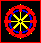
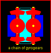
Some alternative constructions. Essence is that in a kind of planetary transmission system (with planet-wheel axles perpendicular on input and output axles), the planet-wheels are heavy fly-wheels, so that Nature takes care of a natural variable braking of the planet-carrier.
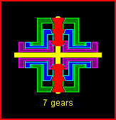
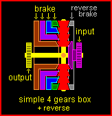
Picture left above is not (yet) a Gyrogear but an 'ordinary' planetary gear with 7 different gears. It can be combined with a Gyrogear and then you have a Gyrogear with 7 different characters. Second picture shows an 'ordinary' 4 gears box (with reverse) wherein a brake, that also is the clutch, varies the ratio. 4 gears can be 5, 6 etc.

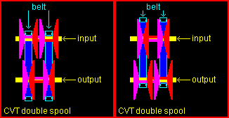
Speaking about CVT systems, I also want to show you the pictures above.
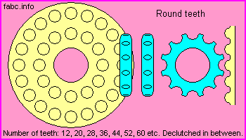
Just a plea for round teeth.
1-10-5
